Hardware hacking tutorial: Dumping and reversing firmware
September 1, 2017
reversing hardware hacking infosec embeddedThe idea
So you might just have an old router or device lying around, and you’re interested what you can find inside. Or, you’re legitimately worried that your devices aren’t safe, or contain some oversight made by engineers in terms of security.
Unfortunately, the latter is very much true, very often. Not by all companies, even by some of the best companies, embedded security is a huge oversight, and an even bigger problem in the years coming, since the number of devices connected to the internet is exponentially growing. And that is scary. Why? Turns out, a lot of devices contain embedded secrets, backdoors and all kinds of dangerous practices made by oversight or just bad engineering.
But fear not, you can check your devices, as long as you’re not reversing them for their IP or to cause any malice.
We can interface with the on-board ports on the device, often left in the open by engineers for debugging or flashing new software. And we’ll cover those in two other tutorials. But what happens when you have no port lying around for you, but you really want to check out that ROM written on the Flash?
Let’s check it out. But we’ll need some gear first.
Used gear
BusPirate
The BusPirate was created by DangerousPrototypes’ Ian Lesnet, and it is a troubleshooting tool that communicates between a PC and any embedded device over 1-wire, 2-wire, 3-wire, UART, I2C, SPI, and HD44780 LCD protocols - all at voltages from 0- 5.5VDC. (SparkFun, n.d.) It will be used for recovering SPI flash data from a router (firmware dumping) and for UART serial communication.
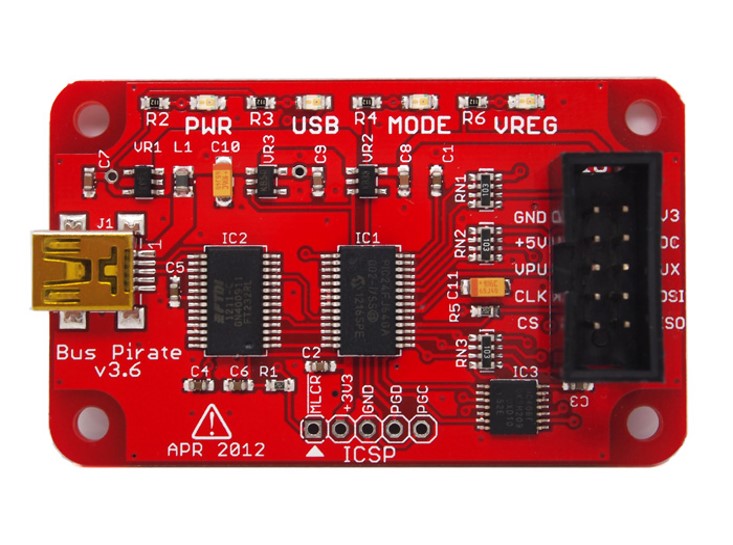
Image taken from: Sparkfun
CJMCU-232H
FTDI 232H is a chip made by Future Technology Devices International. CJMCU-232H is a breakout board with a 232H chip integrated which allows users easily use the chip via USB. It can be used to communicate via USB to UART (RS232, RS422 or RS485), FIFO, JTAG, SPI, I2C, Bit-Bang and many more. It will be used it for UART and JTAG communication with attacked devices.
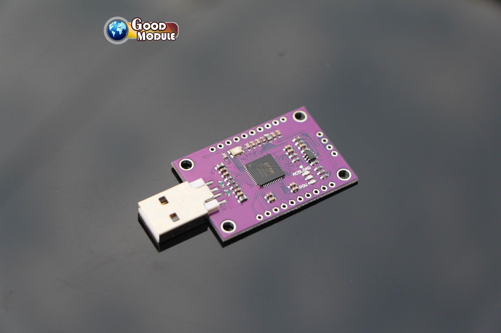
Image taken from: Ebay
Target
The target will be the Mikrotik mAP2n router.
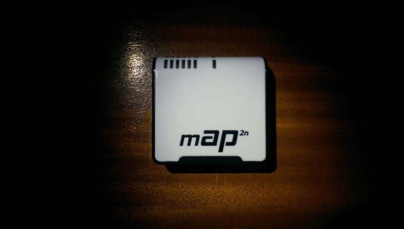
Since the goal is to extract the firmware on it, and check out any other possible attack vectors, some disassembly will be needed first.
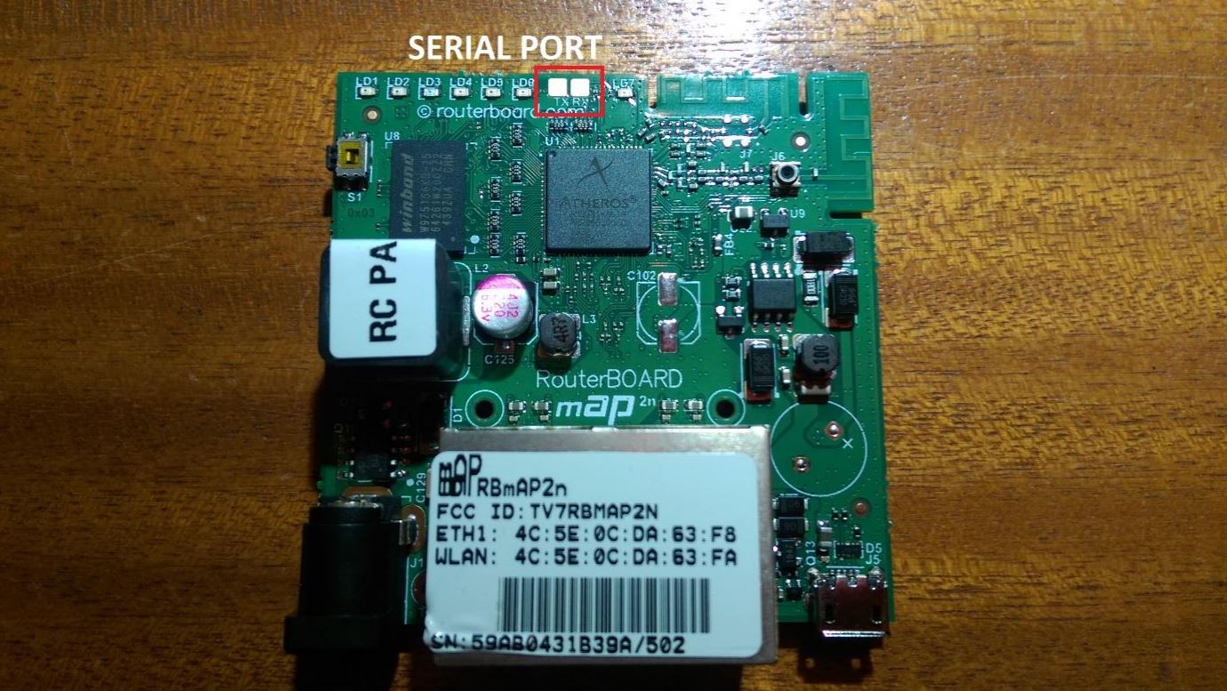
Prying the router open was very easy, and seeing the front side a serial port can almost immediately be seen, marked as TX (transmit) and RX (receive).
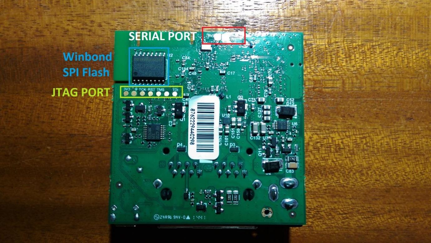
On the backside, the other two pins needed for serial communication can be seen, the power (3V3) and the common ground (GND) pins.
Disclaimer: they are not actually pins, but spots where so-called pogo pin connectors can be placed to achieve connection, but that’s just semantics, and since they don’t really have a defined name, I’ll refer to them as pins. K, thx.
A JTAG port or an interface, can also be seen, marked with 3V3 for the 3.3V power pin, a ground symbol for the ground port, TCK for Test Clock, RST for Test Reset, TMS for Test Mode Select, TDI for Test Data In and an unmarked one which is most probably just the TDO for Test Data Out. JTAG stands for Joint Test Action Group and the interface allows hardware developers to test and diagnose system faults on the board, and to upload data into various memory chips on the board. In this case, it was most probably used to flash the firmware into the SPI flash chip on the board.
Speaking of which, a Winbond 25Q128FVSG Serial Peripheral Interface (SPI) Flash Memory chip can be seen, which is most likely the memory in which the firmware and all the device data are stored.
Interfacing with the SPI Flash Chip
Now the most likely candidate that holds the firmware has been identified, the Winbond SPI Flash chip, it should be easy to find a way to read it and store it outside of the chip. That is where the BusPirate comes in handy. It can be connected to the legs of the SPI SMD chip using Saleae probes and then some software can be used to tell the BusPirate to copy all the data from the chip to the computer. But first, it’s important to understand how to interface the BusPirate to the chip, and how the SPI protocol works.
The SPI Protocol

Image taken from: Sparkfun
The picture above shows a diagram of SPI communication between a Master and a Slave. There are four channels needed:
- SCK which stands for Serial Clock (more often CLK). The side which generates the clock is always the master.
- MOSI – Master-Out, Slave-In (like TX on the serial protocol). MOSI is used when the Master needs to send data to the slave.
- MISO – Master-In, Slave-Out (like RX on the serial protocol). MISO is used when the Slave needs to send data to the master.
- SS – Slave-Select (more often Chip Select, CS) There is always only one master, but there can be several slaves. SS or CS is used to tell the slave to wake up and start sending/receiving data. It is also used to select which slave wants to be communicated with, if there are several.
After gaining a basic understanding of the SPI Protocol, the BusPirate is easily connected to the chip, and the software works out the rest.
BusPirate pinout
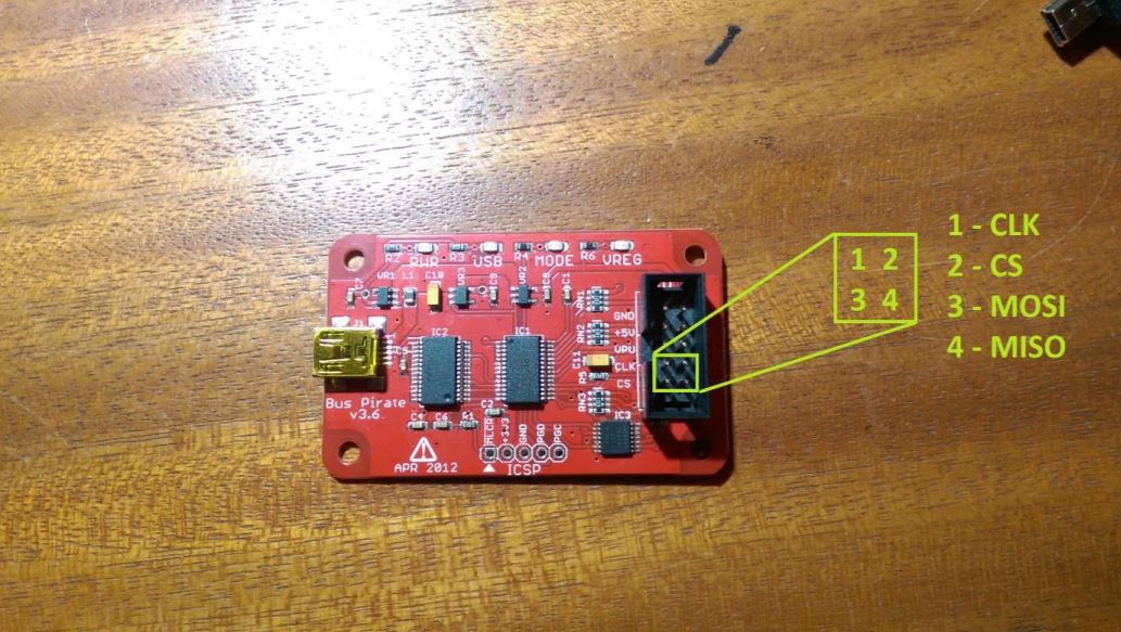
The BusPirate pins are very easy to find, since they are marked right on the board. There are all four pins needed, plus the power (3V3, 3.3 volts) and the common ground pin, which are necessary to provide power to the device and operate it.
Winbond W25Q128FVSG pinout
The Winbond chip on the other hand doesn’t have its pins clearly marked, but the pinout can be found in its datasheet, which is available online.
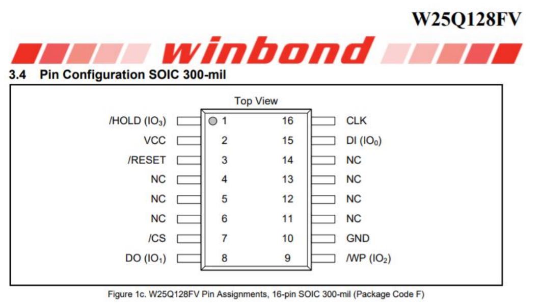
Image taken from: pjrc.com
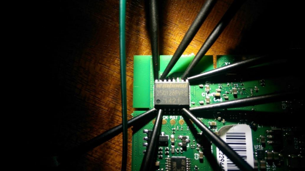
Connecting BP to the SPI Flash
After identifying all the pins needed to interface the BusPirate to the SPI chip, all that remains is to connect them using jumper cables and Saleae probes.
Dumping the firmware /w flashrom
Flashrom is a utility used for identifying, reading, writing, verifying and erasing flash memory chips. It will be used it in conjunction with the BusPirate to obtain SPI Flash chip contents.
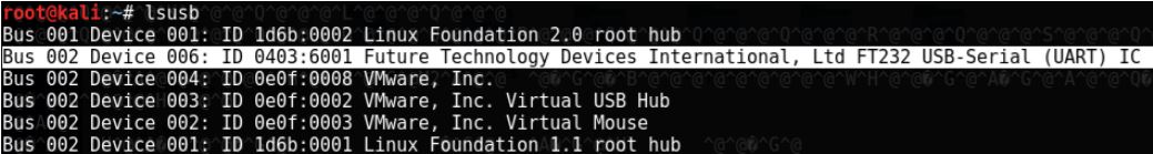
The BusPirate is connected to a laptop running a Kali virtual machine. Running the lsusb command in a Kali terminal, the BusPirate is listed, which means it is recognized and ready to go.
Next, Flashrom will be used in order to try to connect to the BusPirate and see if it recognizes the chip connected to it. If all goes well, that means the pins are connected the right way and are ready for the ‘dumping’ part.
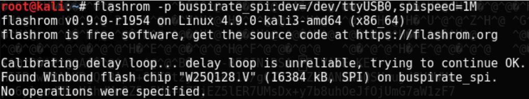
The Flashrom software has indeed found the Winbond flash chip “W25Q128.V” and is ready for use. The flag -p in the command stands for programmer, and it can be used to specify that a BusPirate is connected to a SPI chip, and that it is accessible through /dev/ttyUSB0. Also, the SPI speed is set to 1 MHz, which is the middle ground between reliability and speed. The speed can range from 30K to 8M
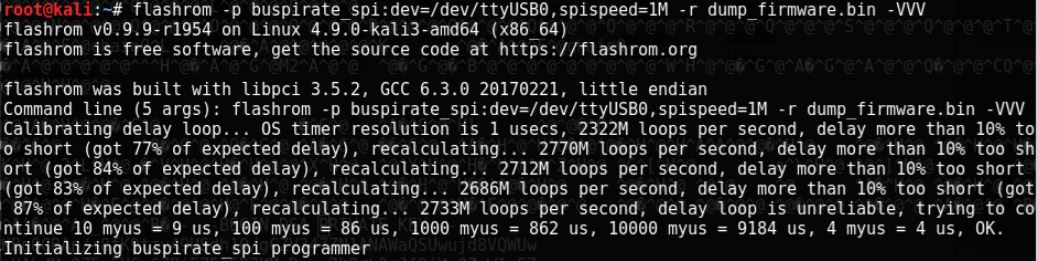
The command used to read out the firmware is the same as the previous one, with two new flags. The first new flag, -r stands for read, which accepts a filename as a parameter into which the contents of the flash ROM are stored. The second flag is -VVV, which stands for verbose, which has multiple levels. The three V is the most verbose level, which will be used since the details of the dumping will be analysed.
The delay loop the BusPirate uses is a bit off, probably since the data is being sent via USB first through the BusPirate to the host OS, and then from the host OS to the virtual machine running Kali. But nonetheless, it manages to recalibrate and factor in the delay of about 14% (14 microseconds per 100 microseconds).
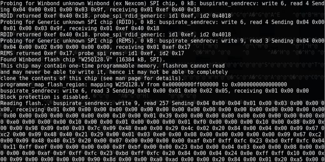
The Flashrom software then continues to probe for various chips, as it did the first time, until it finds the Winbond flash chip. Then it maps the flash region selecting the area of the memory which contains data, checks if block protection is enabled and if all goes well, the BusPirate starts to send the data which is stored into the file passed as the parameter to the -r flag. The data is displayed as a hex stream. Since only 1MHz speed is used, it will take a while until the chip data is copied to the laptop.
Unpacking the binary firmware /w Binwalk
After the BusPirate is finished, the unpacking step can begin, for which Binwalk will be used.
Binwalk is another tool made by Craig Heffner (/dev/ttyS0), and according to him: “Binwalk is a fast, easy to use tool for analysing, reverse engineering, and extracting firmware images.”
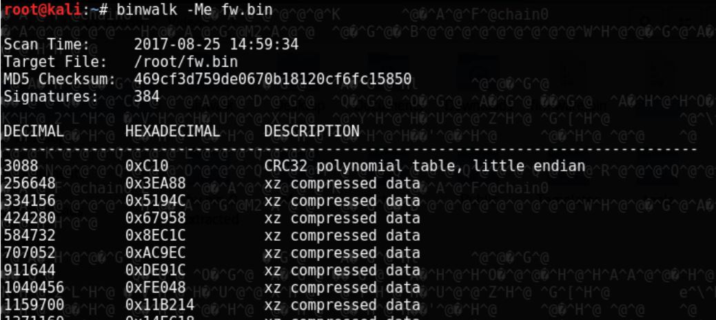
The flag -M stands for matryoshka, which recursively scans extracted files, and if needed extracts the found compressed files. The flag -e stands for extract, which automatically extracts known filetypes.
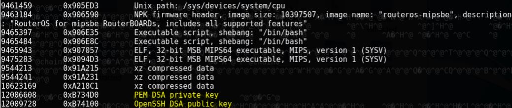
Some files of interest can alredy be seen during the extraction period. One of them is a PEM DSA private key, and an OpenSSH DSA public key, most likely used for authentication and remote control of the device. They can be either carved out using the GNU/Linux tool dd, or manually searched for, among the extracted files.
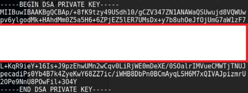
After a little research, a possible use for the key is found. “Since RouterOS 2.9.13 support for SSH DSA keys and passing commands via ssh has been available. This allows you to run scripts from a remote machine against RouterOS without too much trouble anymore.”. (Mikrotik Wiki, n.d.)